Goal
Until this phase, the system only commanded a body. Phase 2 adds the perceptual layer.
A robot that cannot sense its environment is only a motion controller. Phase 2 adds simulated infrared sensors. These sensors let each robot detect obstacles and detect the target object.
Phases 3 to 6 all depend on this phase. Communication, coordination, and search strategy all need information to exchange. That information comes from the sensors.
The core method: ray casting
Ray casting sends an invisible ray from the sensor origin in a given direction. It then answers two questions:
- What is the first object that this ray hits?
- How far away is that object?
Real infrared proximity sensors operate in the same physical way. They send a beam and they measure the return time or the return intensity. The simulation gives exact geometry instead of electronics. For learning the concept, this is better.
Deliverables
By the end of Phase 2, the system has:
- A configurable array of infrared sensors on the robot body.
- A distance to the nearest obstacle from each sensor.
- An infrared beacon on the target object that the sensors can identify.
- Sensor readings displayed in real time.
- Noise that makes the readings realistic.
The PyBullet function
The function rayTestBatch accepts arrays of ray start positions and ray end positions.
It returns one result for each ray. Each result contains:
- The unique ID of the object that the ray hit.
- The hit fraction along the ray.
- The hit position.
- The hit normal.
If the object unique ID is −1, the ray hit nothing. In that case the hit fraction is 1.
Glossary for Phase 2
Norm of a vector. The square root of the sum of the squares of the entries.
Unit vector, also called direction vector. A vector with a length, or magnitude, of exactly 1. It has no dimensional units. Its only function is to describe a direction in space. To create a unit vector, divide a vector by its magnitude.
Sensor frame transform. The global frame, also called the world frame, is a fixed reference frame. It does not change. The body frame, also called the local frame, comes from the position and the orientation of the body that you track. Sensor data often arrives in the global frame. A coordinate transformation is then necessary to align the data with the body frame. The procedure is:
- Capture the initial orientation. Usually you use a static pose in the global frame.
- Calculate the rotation that the sensor needs to match the body frame.
- Apply the transformation.
In this code, the sensor positions are in the body frame. The target position is in the world frame.
Quaternion orientation. Four numbers $(w, x, y, z)$. This is a scalar angle plus a three-dimensional axis vector. Quaternions prevent gimbal lock. They also prevent inefficient transformations.
Euler angles. Euler angles define the orientation of an object in three-dimensional space. They divide the rotation into one rotation for each axis. The system then chains these rotations together. The order is important. The order ZYX does not give the same orientation as the order XYZ. Euler angles cause gimbal lock.
Yaw, pitch, and roll. Yaw is rotation about the Z axis. Pitch is rotation about the Y axis, which moves the nose up or down. Roll is rotation about the X axis. Pilots and aerospace engineers use this form.
Gimbal lock. The loss of one degree of freedom in a three-dimensional system. It occurs when two rotational axes become parallel. It occurs when you track orientation with Euler angles.
Reference. Euler angles and gimbal lock (video)
Questions about ir_sensor.py
These questions came up during the implementation. Each answer explains one concept in the sensor code.
1. What does hit_fraction represent? (Line 13)
rayTest casts a ray from point A to point B. hit_fraction is a number between 0.0 and
1.0. It states how far along the ray the collision occurred, as a fraction of the total
length.
A ──────────────●──────────── B
                ↑
          hit_fraction = 0.6
If hit_fraction = 0.6 and max_range = 2 m, the hit was at 1.2 m. If the ray hit
nothing, hit_fraction = 1.0. This value is the full ray length. It means that no
obstacle is within range.
The value is a fraction and not a distance. This is because the physics engine does not know your units. The engine knows only the geometry.
The result from rayTest is a list with one tuple. The tuple has five fields:
result = p.rayTest(from_pos, to_pos)
# result[0] = (objectUniqueId, linkIndex, hitFraction, hitPosition, hitNormal)
#              int             int        float        (x,y,z)      (x,y,z)
Therefore:
result[0][0]is the object ID. The value is −1 if the ray hit nothing.result[0][2]is the hit fraction.result[0][3]is the exact (x, y, z) world position of the hit.
2. Why do we divide by a norm? (Line 48)
A direction vector must have a length of exactly 1. This is a unit vector. The code uses the vector as follows:
ray_end = origin + direction * max_range
If the direction vector has a length of 2, the ray becomes twice as long as intended.
Division by the norm scales the vector to length 1. The direction does not change.
Example: np.linalg.norm([3,4,0]) = 5. Therefore [3,4,0] / 5 = [0.6, 0.8, 0]. This
vector has the same direction and a length of 1.
3. Why do we use np.array everywhere?
A plain Python list, such as [0.3, 0, 0.1], does not support mathematical operations.
You cannot add two lists element by element. You cannot multiply a list by 3.
np.array makes the list a mathematical vector. All of these operations then work
correctly.
The direction vector and the offset vector each have three components: x, y, and z.
4. What is quaternion rotation? (Line 71)
A quaternion is a representation of a three-dimensional rotation with four numbers. The form is $(x, y, z, w)$.
You do not need the internal mathematics. You need two facts:
[0, 0, 0, 1]means no rotation. This is the identity quaternion.- PyBullet uses quaternions for all orientations. Quaternions do not have the gimbal lock problem of Euler angles.
The function getBasePositionAndOrientation always returns the orientation as a
quaternion.
5. Why transform the sensor position to the world frame? (Lines 80 to 84)
Consider a sensor that is mounted 0.3 m to the right of the robot centre. In the body
frame, relative to the robot, its position is [0.3, 0, 0.1].
Now the robot faces north-east, at 45 degrees. That sensor is no longer 0.3 m east of the robot. It is 0.21 m east and 0.21 m north. The rotation of the robot changed the position of the sensor in the world.
Robot faces East (0°):                Robot faces North (90°):
sensor offset  = [0.3, 0, 0]          sensor offset  = [0.3, 0, 0]
world position = base + [0.3, 0, 0]   world position = base + [0, 0.3, 0]
The function p.multiplyTransforms takes three inputs: the world position of the robot,
the quaternion orientation of the robot, and the body-frame offset. It returns the
correct world-frame sensor position.
You must do this before you call rayTest. rayTest accepts only world coordinates.
A detailed example with numbers
The sensor is mounted 0.3 m forward and 0.1 m to the left of the robot centre. In the
body frame, that position is always [0.3, 0.1]. This value never changes, because the
sensor is attached to the robot.
The question is: when the robot rotates, where is that sensor in world coordinates?
Case 1 — the robot faces east, heading = 0 degrees.
The robot base is at world position [1.0, 1.0].
World Y
   ↑
   |       [Sensor]
   |      ↗
   |    [Robot] → faces East (World X)
   |
   └─────────────── World X
The body frame of the robot aligns with the world frame. Therefore the sensor offset
[0.3, 0.1] maps directly to the world frame:
world_sensor = [1.0, 1.0] + [0.3, 0.1] = [1.3, 1.1]
This is simple addition. No rotation is necessary.
Case 2 — the robot rotates to face north, heading = 90 degrees.
The robot is at the same position [1.0, 1.0]. The sensor offset in the body frame is
still [0.3, 0.1]. But “forward” now means world Y. “Left” now means negative world X.
World Y
   ↑
   |  [Sensor]
   |     ↑  ↑ robot now faces North
   |  [Robot]
   |
   └─────────────── World X
The sensor was 0.3 m forward and 0.1 m left. It is now 0.3 m north and 0.1 m west of the
robot. In the world frame that offset is [−0.1, 0.3], not [0.3, 0.1].
The rotation matrix produces this result:
θ = 90°,  cos(90°) = 0,  sin(90°) = 1

rotated_x = cos(θ) × 0.3  −  sin(θ) × 0.1
          = 0 × 0.3       −  1 × 0.1
          = −0.1

rotated_y = sin(θ) × 0.3  +  cos(θ) × 0.1
          = 1 × 0.3       +  0 × 0.1
          = 0.3

rotated_offset = [−0.1, 0.3]   ← agrees with the geometry

world_sensor = [1.0, 1.0] + [−0.1, 0.3] = [0.9, 1.3]
Case 3 — the robot is at 45 degrees.
θ = 45°,  cos(45°) = 0.707,  sin(45°) = 0.707

rotated_x = 0.707 × 0.3  −  0.707 × 0.1  =  0.212 − 0.071 = 0.141
rotated_y = 0.707 × 0.3  +  0.707 × 0.1  =  0.212 + 0.071 = 0.283

world_sensor = [1.0, 1.0] + [0.141, 0.283] = [1.141, 1.283]
The sensor is diagonally forward and to the right of its start position. This agrees with the geometry of a 45-degree heading.
Why the rotation matrix has this form
The rotation matrix comes from trigonometry. Take a point at distance $r$ along the X axis. Rotate it by an angle $\theta$:
new_x = r × cos(θ)
new_y = r × sin(θ)
For a point with both an x component and a y component, cross-terms occur. A rotation of the x component contributes to both new_x and new_y. The same is true for the y component:
new_x = cos(θ) × x  −  sin(θ) × y
new_y = sin(θ) × x  +  cos(θ) × y
The minus sign on $\sin(\theta) \times y$ occurs because a rotation of the Y component contributes negatively to the new X.
You can verify this. At 90 degrees, a point at [0, 1], which is pure Y, must move to
[−1, 0], which is negative X. Substitute the values:
new_x = 0×0 − 1×1 = −1
new_y = 1×0 + 0×1 =  0     ← correct
What multiplyTransforms does
multiplyTransforms performs the same two operations. It rotates the body-frame offset
by the orientation of the robot. It then adds the world position of the robot.
The difference is that it uses quaternions instead of a 2×2 matrix. Quaternions handle full three-dimensional rotation, which includes pitch and roll. A 2×2 matrix handles only a two-dimensional heading. The internal mathematics is more complex, but the concept is the same: take a body-frame vector, rotate it into the world frame, and add the base position.
6. Where does the ray_end formula come from? (Line 87)
ray_end = sensor_world_pos + rotated_dir * max_range
This is the definition of a ray. Start at a point. Move in a direction for a given distance.
If you stand at position P and face direction D, then the point 2 metres in front of you is $P + D \times 2$. That is the complete formula.
7. What is in the body frame, what is in the world frame, and why?
Body frame. Coordinates relative to the robot. “0.3 m forward from my nose” is in the body frame. The body frame moves and rotates with the robot.
World frame. Fixed global coordinates. “1.5 m east of the arena centre” is in the world frame. The world frame never moves.
Sensor positions are defined in the body frame. This is intuitive, and the values stay constant when the robot moves.
All collision queries, such as rayTest and contact detection, are done in the world
frame. This is necessary because the physics of PyBullet operates in world coordinates.
The quaternion rotation step is the conversion between the two frames.
8. What does result return? (Line 90)
result = p.rayTest(from_pos, to_pos)
# result is a list that contains one tuple:
# result[0] = (objectUniqueId, linkIndex, hitFraction, hitPosition, hitNormal)
#              int             int        float        (x,y,z)      (x,y,z)
Therefore result[0][0] gives the object that the ray hit, and the value is −1 if the
ray hit nothing. result[0][2] gives the fraction along the ray. result[0][3] gives
the exact (x, y, z) world position of the hit.
9. Why is true_distance calculated in that way? (Line 96)
The ray goes from the sensor to a point at max_range metres. hit_fraction gives the
fraction of that distance at which the collision occurred.
Therefore:
\[\text{distance} = \text{hit\_fraction} \times \text{max\_range}\]If the ray is 2 m long and the hit fraction is 0.75, the hit was at 1.5 m.
10. What does ray_draw_end mean? (Line 115)
This is the end point of the debug line in the graphical interface.
The code does not draw the full ray to max_range. It draws the ray only to the position
of the hit. If there was no hit, it draws to max_range.
The expression sensor_world_pos + rotated_dir * distance means: start at the sensor,
and move in the sensor direction for exactly distance metres.
This makes the green, red, and magenta lines in the interface stop at the correct point. Without it, every line would extend the full 2 m.
11. Which body centre? (Line 150)
The body centre of the robot. This is the origin point of the base link in the URDF file.
For the A1 model, this point is approximately the geometric centre of the torso box. All offsets are measured from this point.
12. What does “base” mean in the height value? (Line 151)
Height here means the vertical distance above the base link origin of the robot, in the body frame.
It is not the distance from the ground. It is the distance upward from the torso centre.
The value is 0.15 m. This puts the sensors slightly above the body surface. If the sensors were inside the geometry, the rays would immediately hit the robot itself.
13. How does the sensor angle calculation work? (Line 160)
$2\pi$ radians equals 360 degrees, which is one full circle.
The system needs $n$ sensors at equal spacing around that circle. Divide the circle into $n$ equal parts. Each part is $2\pi / n$ radians wide. Sensor $i$ is at angle $2\pi i / n$.
For $n = 8$:
i=0: angle = 0      = 0°     (points East)
i=1: angle = π/4    = 45°
i=2: angle = π/2    = 90°    (points North)
i=3: angle = 3π/4   = 135°
i=4: angle = π      = 180°   (points West)
i=5: angle = 5π/4   = 225°
i=6: angle = 3π/2   = 270°   (points South)
i=7: angle = 7π/4   = 315°
14. How do the offset and direction calculations work? (Lines 162 to 164)
The functions $\cos(\theta)$ and $\sin(\theta)$ convert an angle into x and y coordinates on a unit circle. Multiplication by the radius gives a circle of the correct size.
θ = 0°:    cos(0)=1,     sin(0)=0    → sensor at (radius, 0, height)   points (1, 0, 0)
θ = 90°:   cos(90)=0,    sin(90)=1   → sensor at (0, radius, height)   points (0, 1, 0)
θ = 180°:  cos(180)=−1,  sin(180)=0  → sensor at (−radius, 0, height)  points (−1, 0, 0)
The offset puts the sensor on the ring. The direction points the sensor straight outward from the centre. This is the same angle. Therefore $\text{direction} = (\cos\theta, \sin\theta, 0)$.
Reference. Polar coordinates, r·cos θ and r·sin θ
15. What does bearing_index mean? (Line 178)
The bearing index is the index $i$ of the sensor that detected the target. Yes, it is the sensor that detected the target.
Each sensor points at a known angle, $2\pi i / n$. Therefore the index of the sensor that fired tells you the approximate direction to the target, relative to the robot. Sensor 0 is at 0 degrees, which is east. Sensor 2 is at 90 degrees, which is north.
This is how the robot knows that the target is to its left. It does not need a camera. It needs only the index of the infrared sensor that fired.
In Phase 3, the robot broadcasts this bearing to the other robot as part of the communication message.
Test configuration
In the first version of the code, Walnut has a fixed gait. Walnut moves in a fixed position. This is important, because the sensors must be stationary. Stationary sensors let you verify that the sensors detect the correct objects. Locomotion adds complexity, so it comes later.
What to observe in the interface
Eight rays come from the robot body in all directions:
| Ray colour | Meaning |
|---|---|
| Green | The ray hit nothing within 2 m |
| Red | The ray hit a wall |
| Magenta | The ray hit the target beacon |
A red sphere moves in a slow circle around the robot. The magenta ray rotates as the target moves around the robot. Two grey walls are at y = ±1.2 m. These walls keep two rays permanently red.
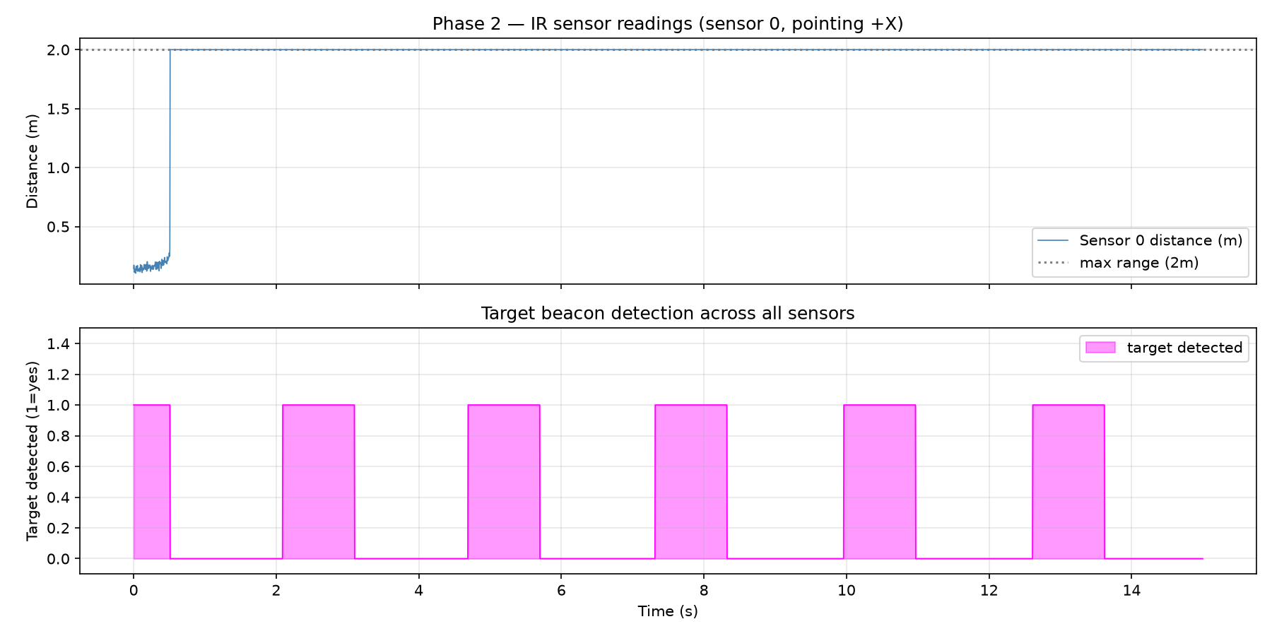
What to observe in the plot
The distance from sensor 0 must oscillate. This happens as the target moves into and out of the sensor cone.
The target detection panel must show regular pulses. There is one pulse for each orbit of the target. Each pulse occurs when a sensor ray moves across the target.
Result
Watch the GUI: green rays = clear, red rays = obstacle, magenta = TARGET

  t=0.0s   sensor0=0.15m  closest=0.00m  target=DETECTED at sensor 0 d=0.15m
  t=1.0s   sensor0=2.00m  closest=0.00m  target=not in range
  t=2.0s   sensor0=2.00m  closest=0.00m  target=not in range
  t=3.0s   sensor0=2.00m  closest=0.00m  target=DETECTED at sensor 1 d=0.18m
  t=4.0s   sensor0=2.00m  closest=0.05m  target=not in range
  t=5.0s   sensor0=2.00m  closest=0.00m  target=DETECTED at sensor 2 d=0.19m
  t=6.0s   sensor0=2.00m  closest=0.01m  target=not in range
  t=7.0s   sensor0=2.00m  closest=0.00m  target=not in range
  t=8.0s   sensor0=2.00m  closest=0.00m  target=DETECTED at sensor 3 d=0.21m
  t=9.0s   sensor0=2.00m  closest=0.00m  target=not in range
  t=10.0s  sensor0=2.00m  closest=0.00m  target=DETECTED at sensor 4 d=0.26m
  t=11.0s  sensor0=2.00m  closest=0.00m  target=not in range
  t=12.0s  sensor0=2.00m  closest=0.01m  target=not in range
  t=13.0s  sensor0=2.00m  closest=0.01m  target=DETECTED at sensor 5 d=0.19m
  t=14.0s  sensor0=2.00m  closest=0.00m  target=not in range

Data saved. Run: python3 phase2/plot_sensor.py
The bearing index increases in order: sensor 0, then 1, 2, 3, 4, 5. This confirms that the target moves around the robot, and that the sensor array measures the bearing correctly.
Commands
cp /mnt/c/Users/ankit/Downloads/ir_sensor.py ~/projects/swarm_robotics/phase2/ir_sensor.py
cp /mnt/c/Users/ankit/Downloads/plot_sensor.py ~/projects/swarm_robotics/phase2/plot_sensor.py

python3 phase2/ir_sensor.py
python3 phase2/plot_sensor.py
explorer.exe phase2/sensor_result.png
Phase 2 summary
The phase produced two classes: IRSensor and IRSensorArray. These are reusable
components. They operate without change on both robots in Phase 3.
Each sensor reads a bearing and a distance. The target ID system separates the beacon from the obstacles. Gaussian noise makes the readings realistic. Debug lines make the rays visible.
The three concepts to learn from Phase 2
- Detection — is an object present?
- Localization — which sensor index gives which bearing?
- Recognition — is this an obstacle, or is this the target?
Next
Phase 3 makes two robots share these readings over a network protocol. Continue to Phase 3 — Communication.